September 17, 2010 - Oxygen Microscope software version 3.1 build 755 is available.
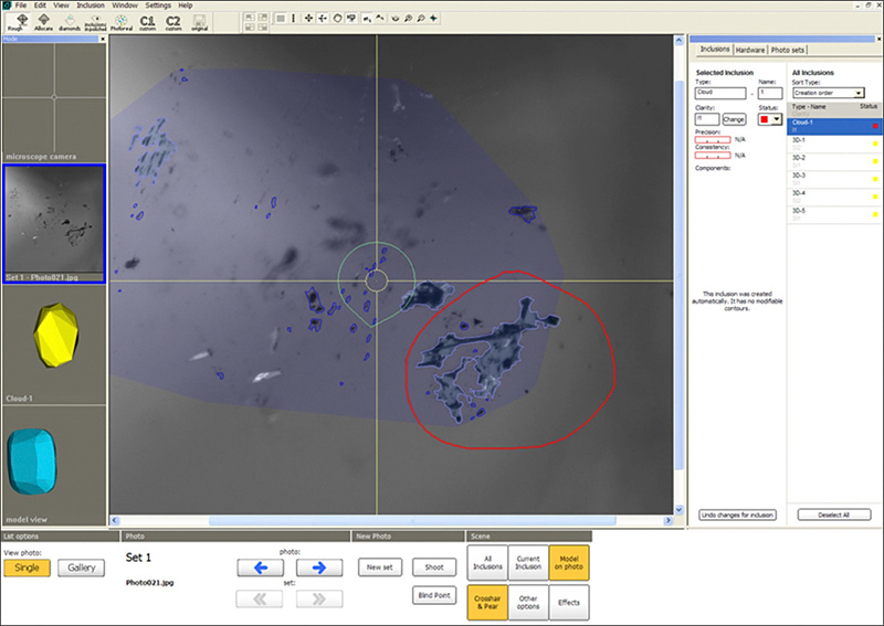
Automatic cloud allocation feature is designed for automatically fast plotting of large groups of point inclusions. Plotting large point clouds like the one you can see on the screenshots below can be extremely time-consuming. With this new feature plotting is done automatically so all you have to do to allocate a cloud is to make a few mouse clicks.
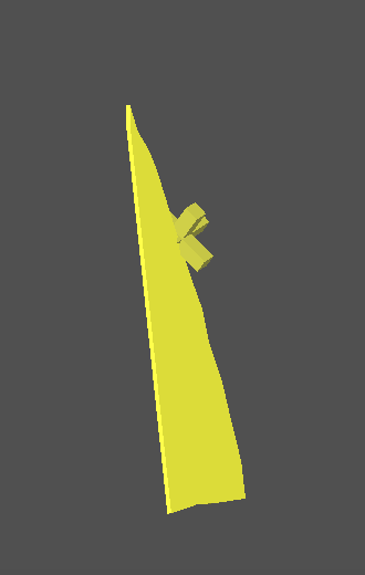
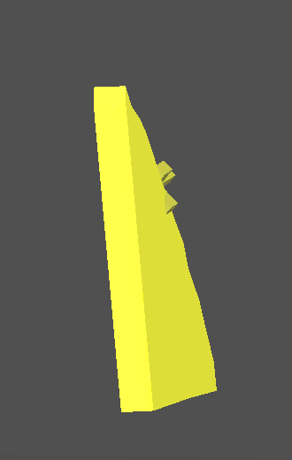
If a cloud inclusion is inside a future diamond it will be photorealistic visualized.
The follow section describes how to create a cloud automatically
Procedure outline:
Step 1. Set cloud position in microscope
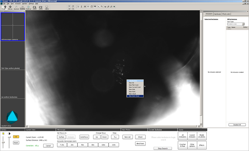
1. Switch to Microscope camera mode and focus on the central part of the cloud
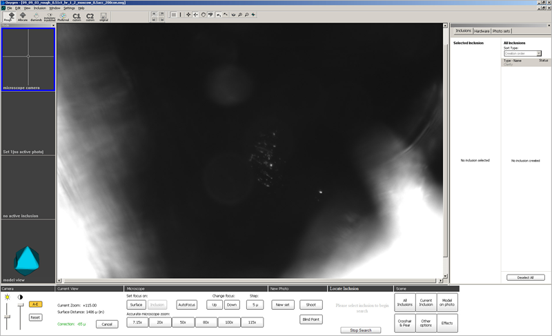
2. Make sure you have chosen an optimal view direction - green pear at the center of the screen. You will not be able to change view direction during auto cloud creation, only focus can be changed.
3. Select New Auto Cloud item from the context menu
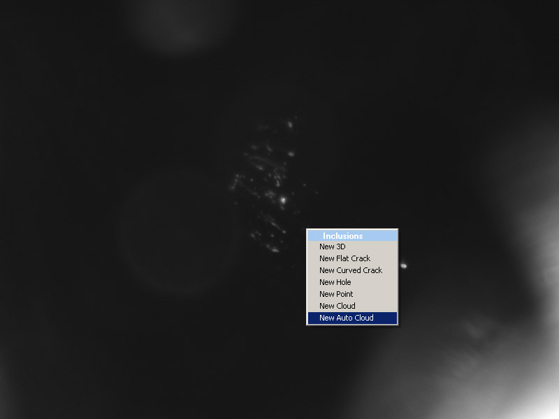
Note. New Auto Cloud item appears in context menu only in Microscope camera mode:
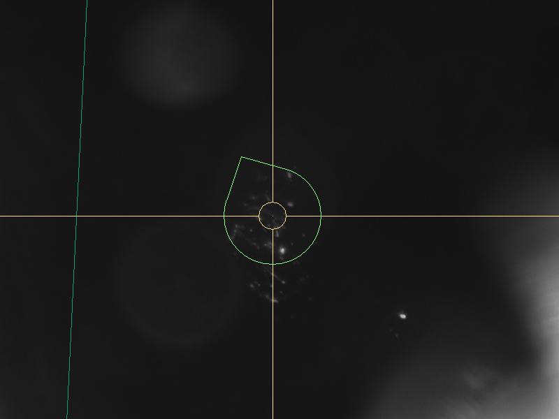
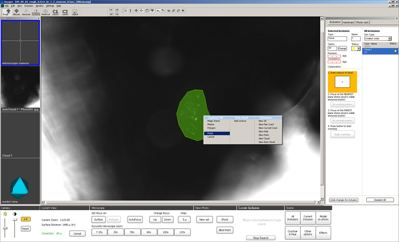
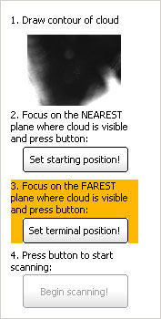
Define cloud contour as shown on the screenshot below
Now specify starting position for scanning:
1. Focus on the beginning of the cloud
We recommend to find the point of the cloud that is nearest to the stone surface and focus on it
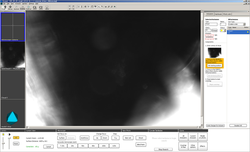
2. Press button Set starting position! at the Inclusions panel

Note: Do not change the translation stage position and do not rotate the stone during step 3 and all the next steps. If you moved or rotated the stone during autocloud creation, an error message would be shown and you would have to enter all the components for autocloud once more. To do it, first click on the thumbnail of cloud contour on the right panel, then repeat the procedure of autocloud allocation from the first step.
In the same way specify terminal position of the scanning:
1. Find the deepest point of the cloud and focus on it
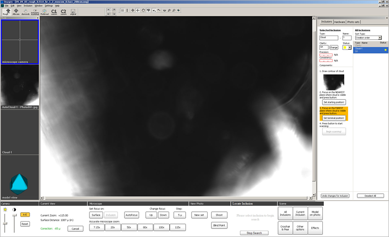
2. Press button Set terminal position! in the Inclusions panel
Step 5. Automatic allocation of cloud
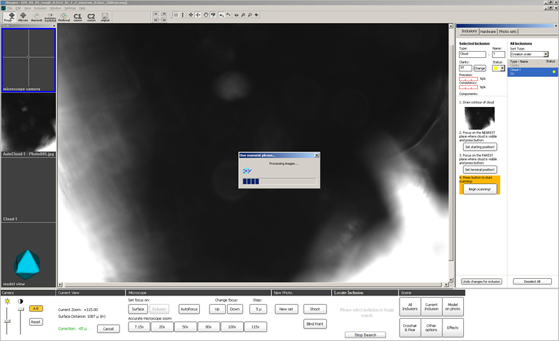
Now press Begin scanning! button and wait
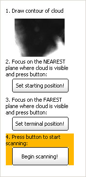
Progress window will be shown to indicate the process of cloud allocation. Allocation process may take from 10 seconds up to 1-2 minutes depending on the cloud size and computer configuration
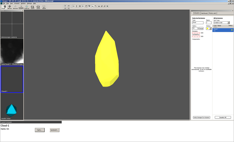
After finishing allocation process inclusion model of cloud is ready
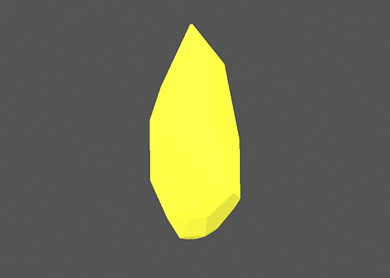
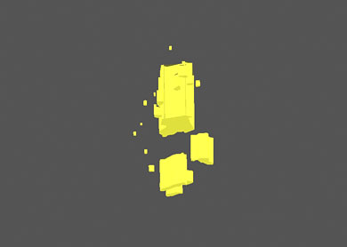
3D models visualization
3D model of allocated cloud inclusion can be observed in two modes:
| Full area of probable location of the cloud | Assumed size |
| Cloud is shown as one inclusion | Cloud is shown as a set of point inclusions |
 |
 |
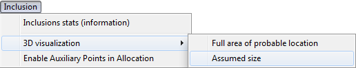
To see cloud in full area size mode select from menu Inclusion / 3D Visualization / Full area of probable location
|
To see cloud in assumed size mode select from menu Inclusion / 3D Visualization / Assumed size
|
Visualization of inclusion contours
To see cloud on photos:
1. Switch to Photo sets tab
2. Find photos that have been taken during the cloud scanning
3. In the center of the screen see the allocation results.
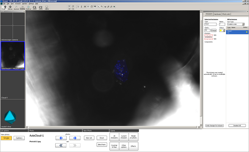
Oxygen displays:
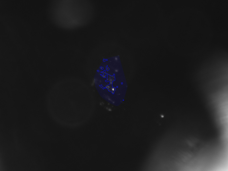
We recommend to look through all cloud photos and make sure that all cloud points are allocated correctly
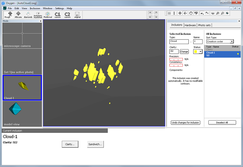
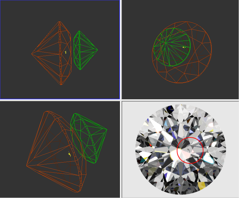
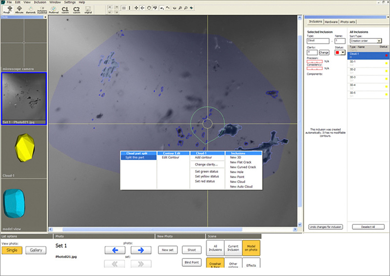
In case some cloud points are located close to each other an automatic allocation tool can accidentally merge them. On the screenshot below you can see that a number of cloud points have been merged into one large 3D inclusion.
In such case please right-click on the cloud part and choose Split this part item in the context menu:
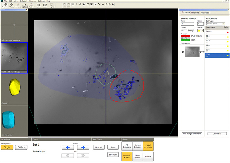
Oxygen will try to split an inclusion into smaller parts.
Splitting procedure results can be seen on the screenshot below.
Added a contrast characteristic of inclusion which affects the Inclusion clarity assigned by automatic algorithms.
The contrast grade affects to:
By default cracks receive Medium contrast, clouds receive Low contrast, all other types - High contrast.
If you need to change contrast of some inclusion manually:
1) Right click on inclusion in Scene and select Change clarity..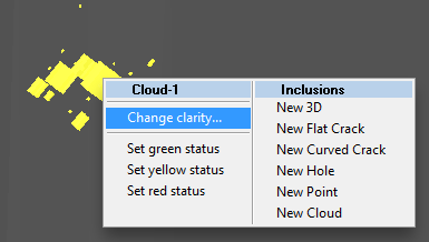
or select an inclusion in list and press button Change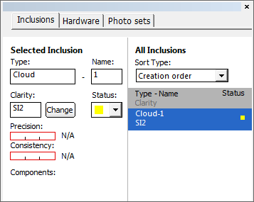
2) Specify Inclusion Clarity window appears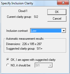
3) Change contrast in the list Inclusion contrast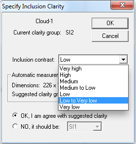
Inclusion sandwiches receives the same contrast and clarity as the initial inclusion. Diamond clarity estimation algorithm consider the whole inclusion rather than separate sandwich parts, so you don't have to adjust contrast of sandiwch ex-parts.
New visual model of Flat crack is available. Now it is thinner.
To view the new visual model of Flat Crack the option Assumed size should be selected from menu Inclusion / 3D visualization / Assumed size:
See an example of visual models of Flat Crack in the new version Oxygen 3.1 and in the previous version Oxygen 3.0:
| New version of Oxygen 3.1 | Previous version of Oxygen 3.0 |
|
 |
Note. Flat cracks created by previous Oxygen versions should be rebuilt to get the new thin visual model.
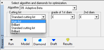
Pacor rough classification cutting lists and yields in Oxygen |
Added ability to use exported .rcf Pacor's rough classification yields and cutting lists instead of Oxygen's built-in cutting / yields lists.
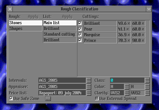
To use the option:
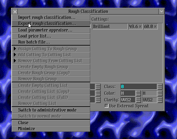
Note. Name of rcf file must be StartRC.rcf