May 14, 2011 - Oxygen Microscope software version 3.2 build 819 is available.
- New creating of cavities
- Improvements of autoexposure algorithm
- 64-bit Windows support
- New Polish reports templates are available in the Oxygen Software
The new special working mode Cavities is designed for creating cavities. Now new cavities are created and modified in this new working mode.
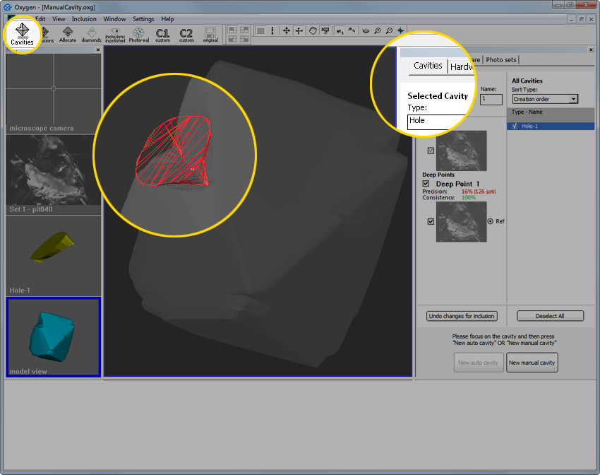
What is new in cavities allocation and construction:
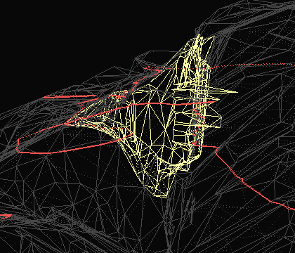
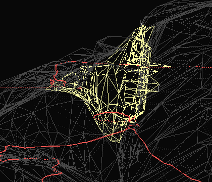
- Automatic creating 3D models of cavities
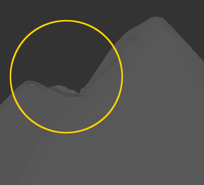
- 3D models of cavities inclusions are cut off from 3d model of rough
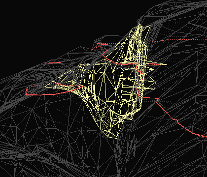
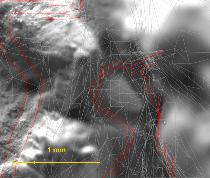
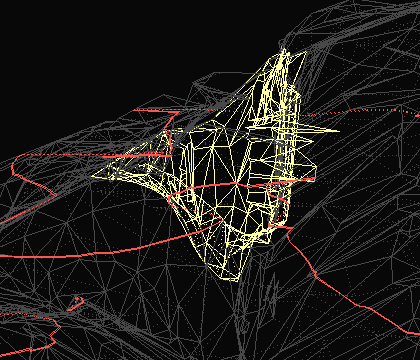
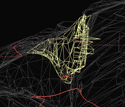
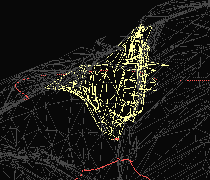
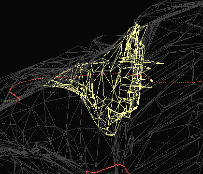
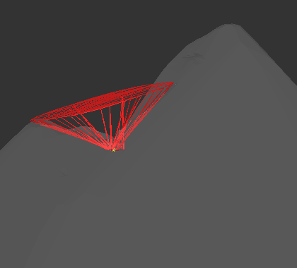
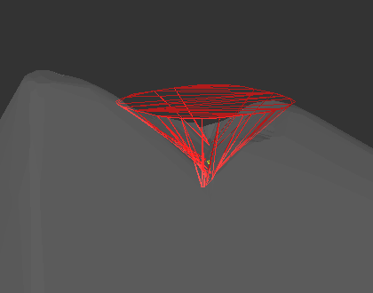
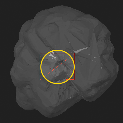
- Wireframe visualization of 3D models of cavities in Cavities working mode
Cavities created in previous versions of Oxygen software are located in working mode Inclusions and can be edited there as well.
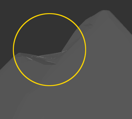
New automatic cavity's allocation tool allows creating surface's cavities that have not been detected by standard Shadow and LM methods and do it automatically. The new tool contains easy-to-use and convenient interface, works fast and accurate. After 3d model of cavity is created it will be cut off from the 3D model of rough diamond. The 3d model of rough became more precise now.
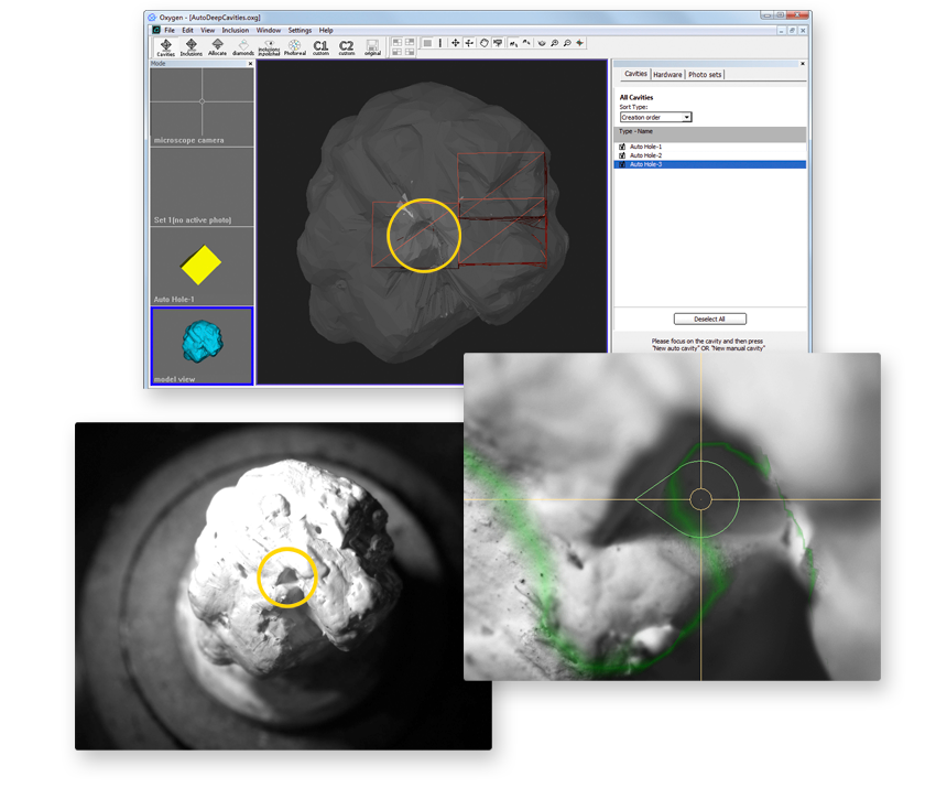
Procedure outline
Step 1. Painting stone in white
Step 2. Locating a cavity in Microscope
Step 3. Automatic building of cavity
Step 4. Verifying cavity's shape by photos
Step 5. Creating large or long cavities
Step 1. Painting stone in white
1) Paint or cover rough diamond with microscopic powder before start working with new cavity automatic allocation option.
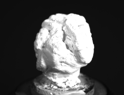
2) Put painted rough diamond into microscope.
Step 2. Locating a cavity in microscope
1) Switch to new Cavities mode

2) Activate Microscope camera view
3) Locate a cavity
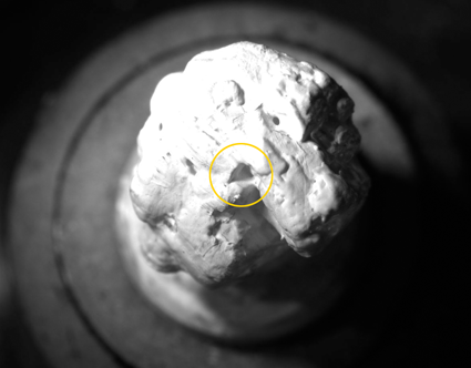
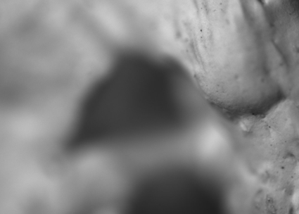
4) Focus on area near surface of cavity. We recommend using magnifications from 50x.
Step 3. Automatic building of cavity
1) Right-click on Scene and select New Auto Cavity in the context menu or press New auto cavity button in right panel.
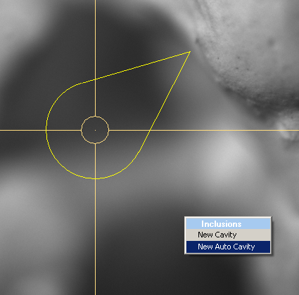
It is possible getting error message: Please decrease the light brightness or flickering effects may occur. See descriptions and suggestions below in the section Possible error message.
2) Wait until scanning is finished.
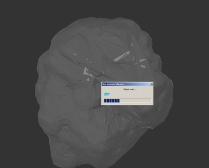
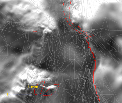
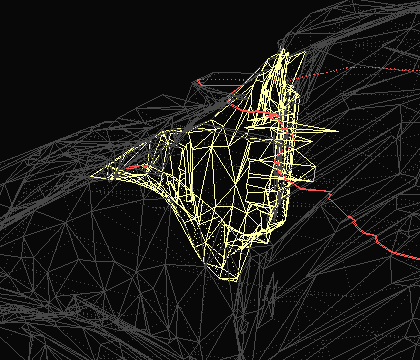
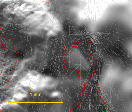
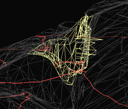
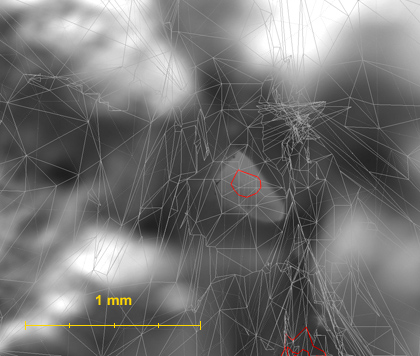
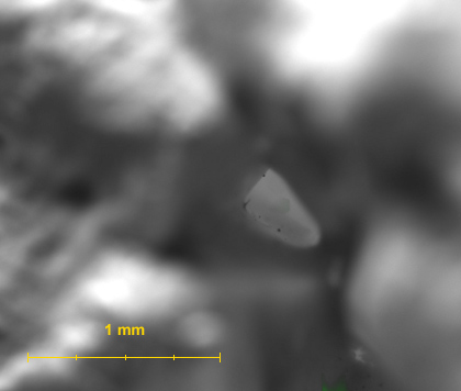
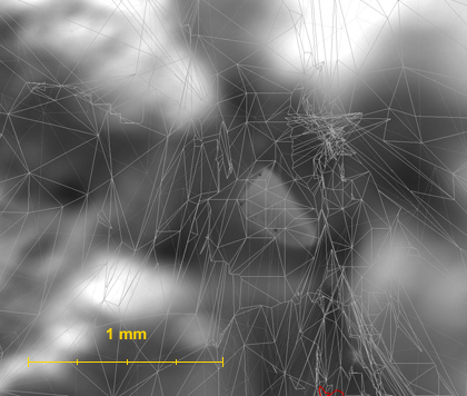
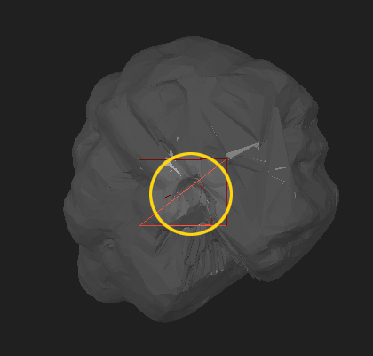
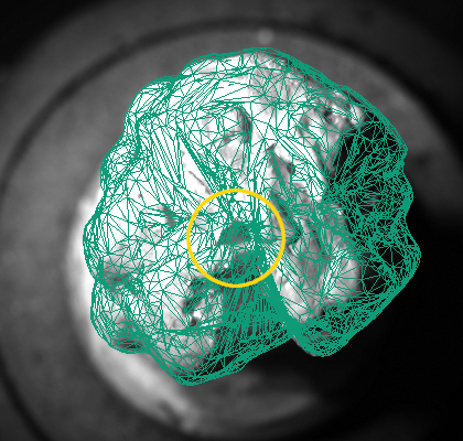
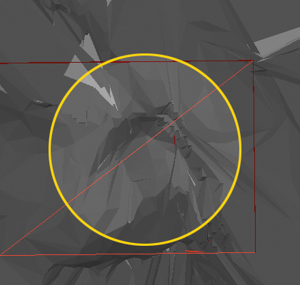
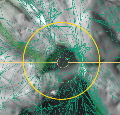
3) Then cavity is ready it's 3d model will be cut off from the 3D model of rough diamond automatically.
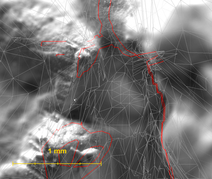
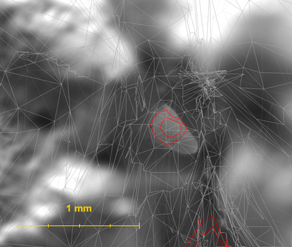
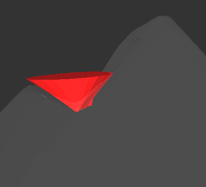
| 3dmodel of cavity | 3dmodel of cavity with photo |
 |
 |
 |
 |
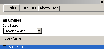
4) New cavity appears in cavities list. To disable or enable cavity use checkboxes:
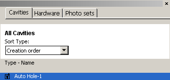
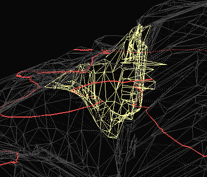
Disabled 3D models of cavities are not cut off from the rough model and don not affect solutions during allocation.
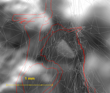
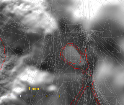
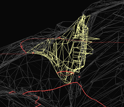
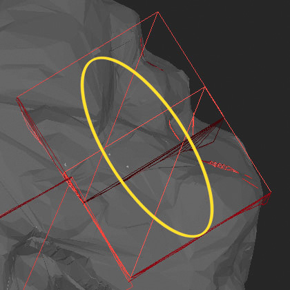
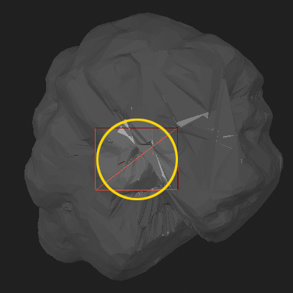
| Enabled 3D model of cavity is cut off from the rough model | Disabled 3D model of cavity is not cut off from the rough model and does not affect solutions during allocation. However, 3D model of disabled cavity is still visible in 3D view in Cavities working mode (red lines) |
 |
 |
 |
 |
Step 4. Verifying cavity's shape by photos
After cavity is built examine shape of the cavity with cavity visualization option. Cavity visualization allows to make sure that cavities on the stone surface are created correctly.
To verify auto cavity's shape:
1) Make active Microscope camera view and select an examined cavity in the list of cavities.
2) Focus on cavity near surface of the rough diamond. We recommend using the magnification factor that has been used for cavity allocation.
3) Start gradually changing focus of the microscope beginning from the topmost part of the cavity until the deepest part of the cavity is reached. We recommend using 50 mkm step during cavity verification procedure.
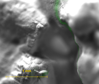
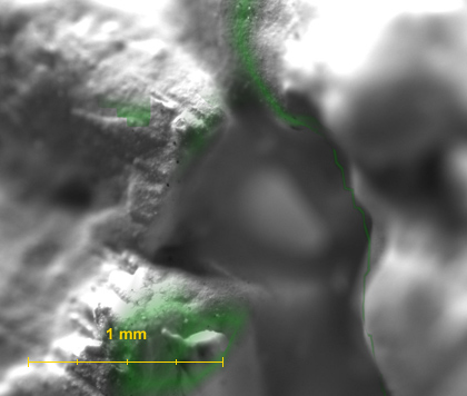
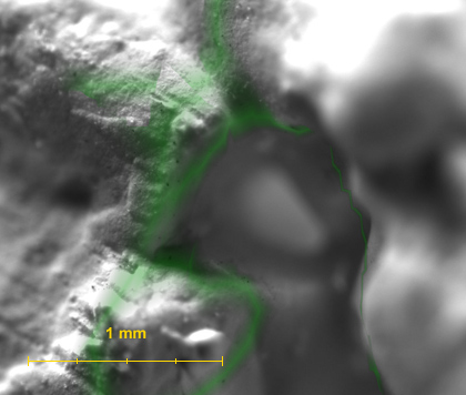
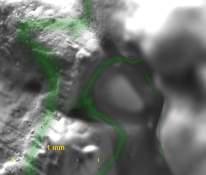
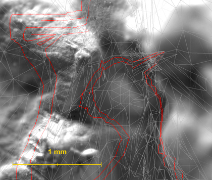
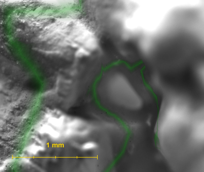
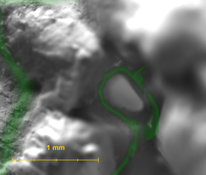
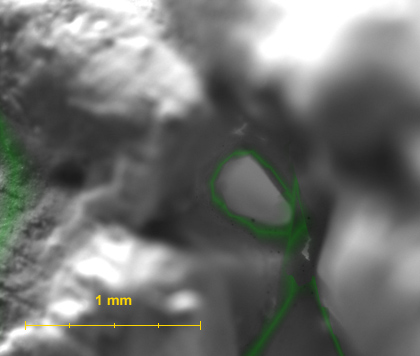
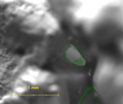
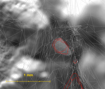
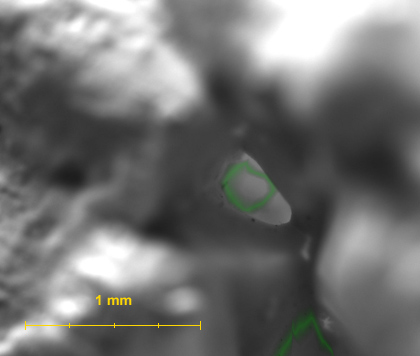
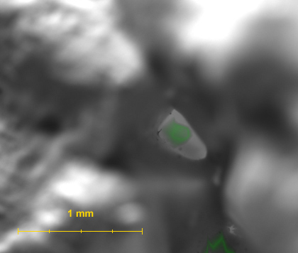
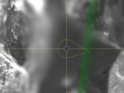
Cavity is displayed as a slice of the cavity surface for each focus position. Green areas marked on images correspond to the intersection of camera focus area with the cavity surface model.
In case of cavity is created correctly green mask on an image coincides with sharp details. See example on the table:

